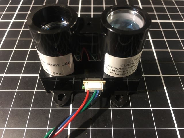
Garmin LidarLite v3
Overview
- Small, lightweight and cheap Laser Range Finder by Garmin
- Pulsed Light ( https://www.pulsedlight3d.com ), the original manufacturer of LidarLite was recently purchased by Garmin, and as as a result, the version 3 is being sold under Garmin brand
- Output: I2C or PWM
- Range: 40m
- Accuracy: +/-2.5cm
- Input Voltage: 4.75 ~ 5.5V (max 6V)
- Power Consumption: 130mA (upto 500mA during initialization)
Versions
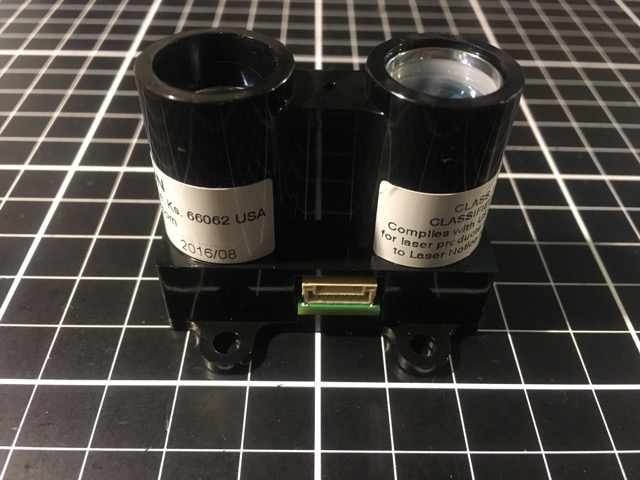
- Black Label = V1 (Shiny silver sticker with black lettering)
- Blue Label = V2
- White Label = V3
Known Issues
- Both V1 and V2 have issues with unstable power source, resulting
errors or freezes
- If the reading has a 13m offset, make sure the input voltage never goes below 5V.
- V1 is noisy and interferes with GPS
- V2 (Blue Label) has unstable I2C connection, so use PWM
- V3 should have these issues resolved, but it needs more testing
- First batch? of V3 behaves more like v2 as it responds to hardware and software version register query. V3 units supposedly have these eliminated. The contents of the hardware version register on these early units is 0x15 and the software version register is 0x02
- You need AC3.5-rc2 and later in order to use newer V3 units
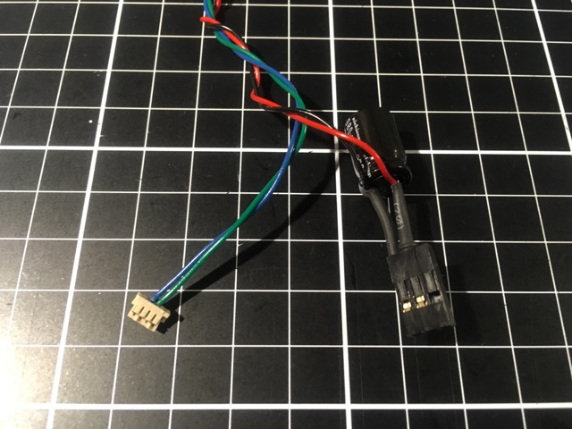
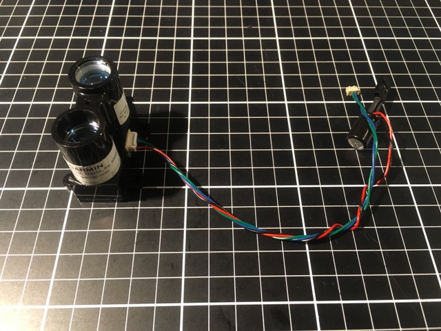
Connection
V3 wiring
What’s needed
- 680μF Capacitor x 1
- Servo Connectors (When using PWM, or if the Pixhawk’s servo rail is already powered by a stable BEC), or use a dedicated 5V BEC
- Pixhawk Connectors
- Pixhawk: Hirose DF13 4 pin housing and crimp terminals
- Pixhack, PixRacer, Pixhawk 2.1: JST GH 4 ping housing and crimp terminals
I2C Connection
- If Pixhawk’s servo rail is already powered by 5V BEC for powering servo and/or as a backup power source, simply power LidarLite off the servo rail
- When crimping the servo connector to LidarLite’s power leads, crimp capacitor’s leads together
- It more or less works when powered off of Pixhawk’s I2C port, but
it’s not recommended
- Garmin’s Arduino sample library mentions
(Capacitor recommended to mitigate inrush current when device is enabled)
- Garmin’s Arduino sample library mentions
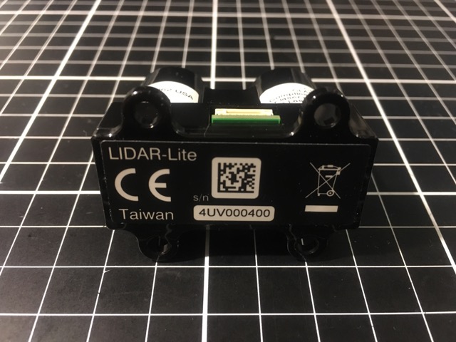
LidarLite Pinout & Cables
| Cable Colour | Signal |
|---|---|
| Black | GND |
| Blue | I2C SDA |
| Green | I2C SCL |
| Yellow | PMW Mode |
| Orange | Enable |
| Red | 5V Vcc |
Connection (Pixhawk - DF13)
Connection Reference
LidarLight Diagram
- http://www.robotshop.com/media/files/pdf2/lidar_lite_v3_pinout.pdf
- http://www.robotshop.com/blog/en/lidar-lite-v3-available-for-pre-order-19202
Pixhawk Ports Details
NOTE: The diagrams on the page below is for V1 and V2 which have Molex Clickmate connectors, while the V3 has JST GH connector and their pinouts are different, so be sure to refere to the information above if you are using V3
Parameters
I2C
RNGFND_TYPE = 3  # I2C Driver (for V2 and early V3 units)
RNGFND_TYPE = 15 # I2C Driver (for newer V3 with AC3.5-rc2 and later. Skips version detection and forces V2 behavior)
RNGFND_MIN_CM = 20 # 20cm
RNGFND_MAX_CM = 4000 # 4000cm = 40m
RNGFND_OFFSET = 0
RNGFND_GNDCLEAR = 10 # The distance to the Lidar from the ground. Minimum 20cm recommended

RNGFND_SCALING = 1 # Adjust between 0.8 ~ 1.0
RNGFND_GAIN = 0.5 # Increase this value to make the vehicle respond quicker to changes in ground height. Setting this too high could make altitude control unstable

EK2_ALT_SOURCE = 1 # Use Range Finder for altitude measurement. The doc says it's only available when using OpticalFlow, but that's not true. It works with Alt_Hold, PosHold, and Loiter. Set this to 0 for baro, 2 for GPS

# Copter 3.4 and later
EK2_RNG_USE_HGT = 50 # 0 ~ 100% of the RNGFND_MAX_CM
                     # Rangefinder becomes the primary height source when below this level
                     # i.e. If RNGFND_MAX_CM = 4000 and EK2_RNG_USE_HGT = 50, then RangeFinder becomes primary height source below 20m
                     # Only use it while flying slowly
                     # Default is -1 which disables using RangeFinder as height source

EK2_ALT_M_NSE = 3 # Barometer noise in meters. Increase this to rely less on baro and more on GPS and accelerometers
EK2_RNG_M_NSE = 0.5 # Increase this if you have a noisy rangefinder
EK2_TERR_GRAD = 0.1 # Increase this if the ground below the vehicle is not flat

EK2_RNG_I_GATE = 500 # If rangefinder mesurements are off by this amount, EKF rejects the distance data. Leave at default unless you know what you are doing
EK2_HGT_I_GATE = 500 # See above
PWM
BRD_PWM_COUNT = 4
RNGFND_TYPE = 5 # PWM Driver
RNGFND_PIN = 54 # PWM input = Pixhawk AUX5
RNGFND_RMETRIC = 1 # Set this to 0 for SF/02
RNGFND_MIN_CM = 20
RNGFND_MAX_CM = 4000
RNGFND_OFFSET = 0
RNGFND_GNDCLEAR = 10
RNGFND_STOP_PIN = -1 # Don't use this, unless you really need to minimize power consumption or if your Lidar keep freezing. This will reset the unit if there's no reading.

# If you have Terrain Data available via GCS and want to conserve battery
RNGFND_STOP_PIN = 55 # Pixhawk AUX6 (Optional)
RNGFND_PWRRNG = 20 # Put Lidar to sleep above 20m

RNGFND_SCALING = 1 # Adjust between 0.8 ~ 1.0
RNGFND_GAIN = 0.5 # Increasing this will cause the vehicle to more quickly respond to the ground height changes.

EK2_ALT_SOURCE = 1 # Use Range Finder for altitude measurement. The doc says it's only available when using OpticalFlow, but that's not true. It works with Alt_Hold, PosHold, and Loiter. Set this to 0 for baro, 2 for GPS.

# Copter 3.4 and later
EK2_RNG_USE_HGT = 50 # 0 ~ 100% of the RNGFND_MAX_CM
                     # Rangefinder becomes the primary height source when below this level
                     # i.e. If RNGFND_MAX_CM = 4000 and EK2_RNG_USE_HGT = 50, then RangeFinder becomes primary height source below 20m
                     # Only use it while flying slowly
                     # Default is -1 which disables using RangeFinder as height source

EK2_ALT_M_NSE = 3 # Barometer noise in meters. Increase this to rely less on baro and more on GPS and accelerometers
EK2_RNG_M_NSE = 0.5 # Increase this if you have a noisy rangefinder
EK2_TERR_GRAD = 0.1 # Increase this if the ground below the vehicle is not flat

EK2_RNG_I_GATE = 500 # If rangefinder mesurements are off by this amount, EKF rejects the distance data. Leave at default unless you know what you are doing
EK2_HGT_I_GATE = 500 # See above
Others
Angle Compensation
- Went into 3.4
Reference
- https://www.pulsedlight3d.com
- https://github.com/PulsedLight3D/LIDAR-Lite-Documentation/blob/master/Docs/LIDAR-Lite-v2-Docs.pdf
- https://www.garmin.com/en-US/blog/general/announcement-lidar-lite-v3/
- https://support.garmin.com/support/manuals/manuals.htm?partNo=010-01722-00&language=en&country=US
- http://static.garmin.com/pumac/LIDAR_Lite_v3_Operation_Manual_and_Technical_Specifications.pdf
- http://www.robotshop.com/blog/en/lidar-lite-v3-available-for-pre-order-19202
- http://www.robotshop.com/media/files/pdf2/lidar_lite_v3_pinout.pdf
- http://www.robotshop.com/media/files/pdf2/pli-06-instruction.pdf
- https://www.sparkfun.com/products/14032
- http://ardupilot.org/copter/docs/common-rangefinder-lidarlite.html
- https://github.com/ArduPilot/ardupilot/issues/1277
- http://discuss.ardupilot.org/t/error-terrain-alt-variance/11933/12
- http://discuss.ardupilot.org/t/altitude-hold-unreliable-in-fast-flight-how-to-tune
- https://pixhawk.org/modules/pixhawk